The media discontinuity slowing down pipeline construction — and how we eliminate it
The planning is perfect — until the site measurer discovers that reality looks different on site. Their changes end up on paper, and from that moment on, the risk begins. pAIpe puts an end to media discontinuity.
Everyone involved in piping construction knows this problem
The isometric drawing comes from engineering, perfectly planned on the computer and cleanly derived from the 3D model. On paper, everything looks consistent. But in piping construction, planning and reality rarely match one-to-one — and precision down to the millimeter matters here. The requirement is always the same: stress-free installation.
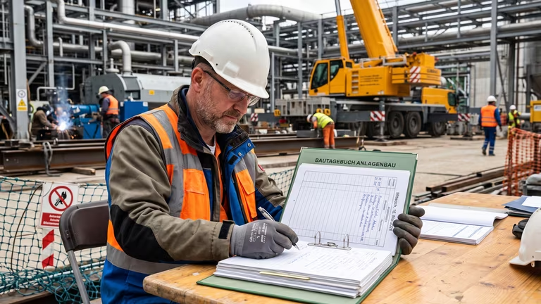
So the field measurer heads out. He takes the plans with him, compares them with the actual site conditions, measures again, makes corrections. Hours go into preparation, measuring, and rework. In the end, he puts his changes on paper — and that’s exactly where the real problem begins.
From the moment the pen touches the paper, it becomes risky
Because from that point on, the truth exists on a single A3 isometric sheet. One sheet that moves around the construction site, gets passed from hand to hand, can get soaked in the rain, disappear in a stack of papers — or simply get lost.
And then what? Then everything gets done again. The field measurer drives back out, measures everything again, redraws everything again. Hours of work, duplicated.
But even if the paper makes it back: someone in the office still has to read the hand drawing, interpret it, and transfer it into the system. What nominal diameter does that say? Is that a 3 or an 8? Was that elbow 45° or 90°? Every transfer is a potential source of errors. And every error costs money — material, time, and in the worst case, rework on site.
That’s the media disruption: The moment when a fully digital workflow breaks down and everything depends on a single sheet of paper of which only one copy exists.
We eliminate that disruption
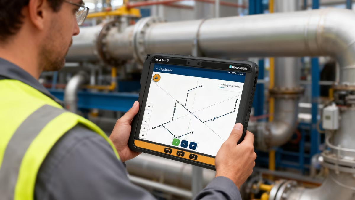
With pAIpe, the field measurer takes a tablet onto the construction site. Instead of pen and isometric paper, he draws the isometric directly in the app — using drag & drop with real components.
He taps on the canvas, drags a pipe in the desired direction, and the system automatically detects the axis. Need a tee, a valve, or a flange? Tap the radial menu, select the component, drag it onto the pipe — done. The pipe is automatically split, the connections created, and the welds generated.
And the key point: The drawing is automatically transferred to the web platform and is immediately available to everyone involved. No scanning, no manual typing, no “Can you figure out what this says?”
No interpretation, no reading errors
What is drawn on the tablet is not an image — it is structured data. Every pipe has a nominal diameter, every flange a DIN type, every weld a category. From pipe segments, elbows, tees, and reducers to flanges and valves — everything the field measurer needs on site is available as a component and automatically linked correctly when placed.
Because the data is structured, every drawing automatically generates a complete bill of materials — grouped by pipes, elbows, tees, flanges, and valves. Pipe lengths are totaled, identical components consolidated. No manual counting, no Excel.
Welds and spools — already defined during data capture
Every connection between two components automatically becomes a weld. The field measurer only specifies whether it is a shop weld, site weld, or field fit weld. The spool breakdown is then generated automatically — shop welds define the boundaries, everything else does not.
That means the fabrication information is already embedded in the drawing before anyone in the office even touches it. Pipe book, welding plan, material requisition — everything can be derived from a single source.
What changes as a result
Instead of a single truth existing on one A3 sheet, the data is captured digitally and synchronized immediately. Instead of handwriting that someone has to interpret, the system contains structured, unambiguous values. The bill of materials is generated automatically — no more manual compilation. And if a drawing gets lost? That no longer happens because it is available to everyone involved at any time. Welds no longer need to be documented separately; they are already embedded directly in the drawing. And the office no longer waits for the field measurer to return — the data is available immediately.
Not a CAD replacement — a tool for the construction site
The isometric module does not replace an engineering tool. It closes the gap that is currently bridged with paper and hope. If the field measurer can capture his work digitally — with real components, real dimensions, and real welds — then the most dangerous moment in the entire process disappears: the media disruption.
Whether it’s the bill of materials, pipe book, or dimensions: no interpretation, no reading errors.